Introduction
Mesh Modeling typically begins with a Mesh Primitive shape (e.g. circle, cube, cylinder...). From there you might begin editing to create a larger, more complex shape.
Modeling Modes
The 3D View has three principal modes that allow for the creation of, editing and manipulation of the mesh models. Each of the three modes have a variety of tools. Some tools may be found in one or more of the modes.
Modes that used for modeling:
- Object Mode
- Edit Mode
- Sculpt Mode
Creation of a mesh primitive typically starts by adding a mesh object in Object Mode. Limited types of editing such as size, location, and orientation can be accomplished in Object Mode. Object Mode also provides the means to Join and Group multiple mesh primitives.
More detailed editing of the mesh model shape is done in Edit Mode, and Sculpt Mode. The nature of these three modes determines the tools that are available within the various panels of the 3D View. Switching between modes while modeling is common. Some tools may be available in more than one mode while others may be unique to a particular mode.
You can work with geometric objects in two modes.
Object Mode
Object Mode Operations in Object Mode affect the whole object. Object Mode has the following header in the 3D View:

Object Mode Header.
Edit Mode
Operations in Edit Mode affect only the geometry of an object, but not global properties such as location or rotation.
You can only modify the mesh of the object you are editing. To modify other objects you need to leave, select them and re-enter Edit Mode.
Edit Mode has the following header in the 3D View:

Edit Mode Header.
Tools and modes in the 3D View header are (left to right):
- View, Select, and Mesh menus
- Blender Mode
- Display method for 3D View
- Pivot center
- 3D manipulator widget
- Selection mode
- Limit Selection to Visible
- Proportional editing
- Snap
- OpenGL render
You can switch between the Object and Edit Modes with Tab.
You can change to any mode by selecting the desired Mode in the menu in the 3D View header.
Visualization
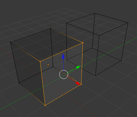
By default, Blender highlights selected geometry in orange in both Object Mode and Edit Mode.
In Object Mode with Wireframe shading enabled Z,
objects are displayed in black when unselected and in orange when selected.
If more than one object is selected, all selected objects except the active object,
typically the object last selected, are displayed in a darker orange color.
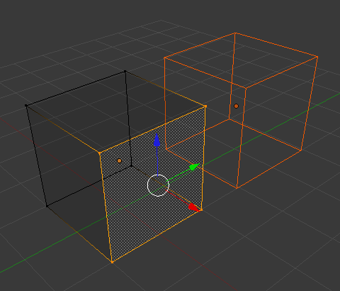
Similarly, in Edit Mode, unselected geometry is drawn in black while selected faces, edges, or vertices are drawn in orange. The active face is highlighted in white. If two vertices joined by an edge are selected in Vertex selection mode, the edge between them is highlighted too. Similarly, if enough vertices or edges are selected to define a face, that face is also highlighted.
If multiple objects are selected before entering Edit Mode, all the selected objects remain highlighted in orange indicating that they are part of the active selection set.
Tool Shelf

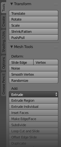
The Tool Shelf panel in edit mode.
Open/close the Mesh Tools panel using T.
When entering Edit Mode, several mesh tools become available.
Most of these tools are also available as shortcuts
(displayed in the Tooltips for each tool) and/or in the Specials menu
W, the Edge menu Ctrl-E, and Face menu Ctrl-F.
The properties of each tool are displayed in the operator panel at the bottom of the Tool Shelf.
Even more mesh editing tools can be enabled in the .
Properties Region

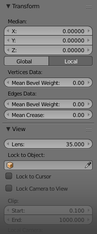
The Properties region in edit mode.
Open/close the Properties region using N.
In the Properties region, panels directly related to mesh editing are the Transform panel, where numeric values can be entered, and the Mesh Display panel, where for example normals and numeric values for distances, angles, and areas can be turned on.
Other useful tools are found in the Properties Editor under the Object and Object Data tabs, including display options and Vertex groups.

